Well, diode method didn't work for other versions of FD-235.
Are you sure about pin8?
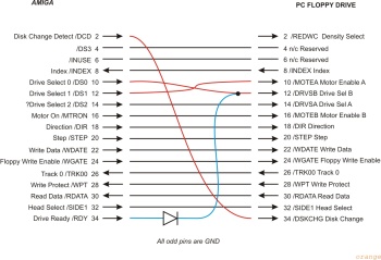
Yeah, pin8 = INDEX.
The way it's shown on the pic (using the drive's SELECT signal) is not a good idea.
The typical sequence is:
1. Select the drive
2. Enable the motor
3. Wait for the RDY signal (or for 500 milliseconds) to ensure that the motor is up to full speed
Some drives may have the motor ready in as little as 300 ms, but that's about it.
So the soonest possible after Select before the drive (motor) is actually Ready is about 300 ms, and that's not even valid for all drives. 500 ms is the accepted delay.
So, if you tie RDY to SEL, you're essentially telling the Amiga that the drive is Ready as soon as it's Selected, which is obviously not true. So an RDY-based loader will read bogus data, and it all boils down to whether the loader has a recovery procedure or not. If it has, it'll retry and retry until the motor is in full speed, at which point valid data will come through and the loader will continue.
Otherwise, if it operates under the assumption that data is always correct, you'll get a nice crash.
To the contrary, the RDY signal is always a prerequisite before the drive issues an INDEX signal (even if RDY is not externally provided, the motor-readiness state is still assessed before any valid INDEX signal is issued).
So tying INDEX to RDY, you avoid the aforementioned risk.
