NO! You haven't putted them right!!! READ BELLOW!There is no IDE cable in the schematic.
Maybe you're mistaken the clockport ribbon with it

Anywayz, if you connected the Subway correctly (for the clockport part) then you only miss the USB headers on it.
USB cable has 4 wires...
You can check out their coloring scheme from the following diagram...

so...
we have Red, White, Green and Black (and sometimes depending on the cable one more Black which is GND).
So as you can see from the photo I supplied earlier from E3B's website you can see the Subway's right connectors (Not the clockport ones but the USB header ones) are putted looking it from above like that:
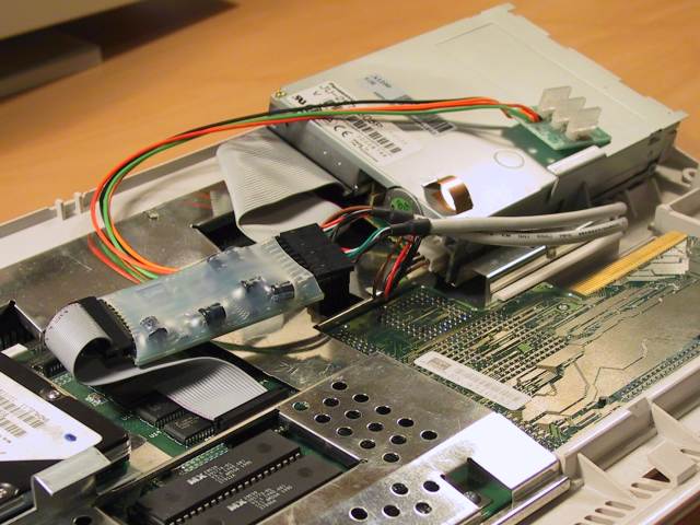
Red, White, Green, Black.
NOTE: If you have a 4wire cable instead of 2 (as I seen from your pictures), you can leave open the 5th pin in every header.
So if you have for example a 4x 4wire pin connectors you should connect them like:
Row 1: Red, White, Green, Black, Open, Red, White, Green, Black, Open
Row 2: Red, White, Green, Black, Open, Red, White, Green, Black, Open
You understood now a bit better?
EDIT: I made the following edit based on your picture... Sorry for the ****y editing... I wanted to make it fast

