|
|
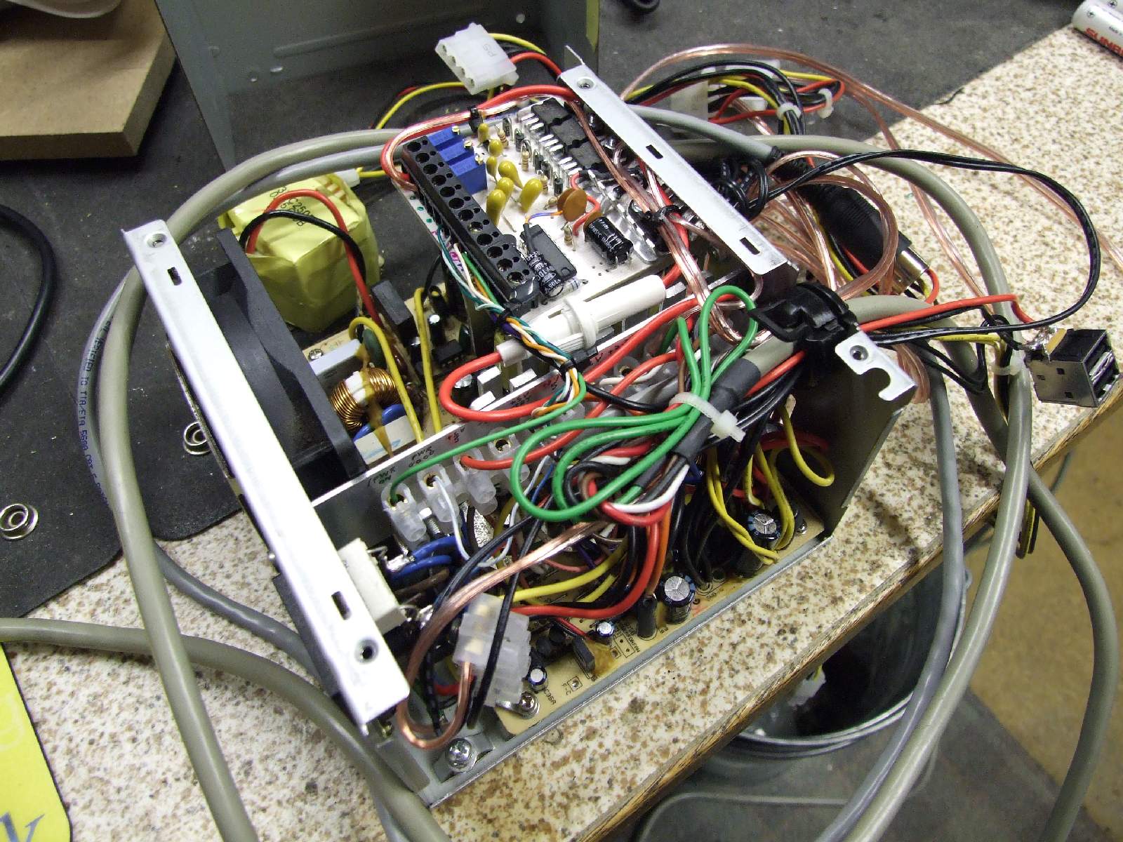
| ATX PSU Mod stage 1 complete | ||
 |
||
| Previous Image | Next Image | ||
|
Description: Rather than rambling on I'll give you folks a chance to ask a question or two :-D
Picture Stats: Views: 2998 Filesize: 289.33kB Height: 768 Width: 1024 Posted by: Hodgkinson at February 04, 2008, 08:51:15 AM Image Linking Codes
|
||
| 0 Members and 1 Guest are viewing this picture. |
| weirdami Posts:3776 | May 13, 2008, 04:41:59 AM It's either super awesome modtastic funtime fun or you ate the wrong frog. :-D |
| Hodgkinson Posts:1080 | March 30, 2008, 09:52:31 AM The other end of the project: The control panel. |
| Hodgkinson Posts:1080 | March 11, 2008, 09:23:15 PM Project update It would seem that the PSU that this project is based around (Bestec 250W ATX) is notorious for frying systems. I've just uploaded a photo of the beginnings of the MKII ATX PSU Mod project, based around a different PSU. This (MKI) project will now have to be dismantled to build the new project :boohoo: Hodgkinson. |
| delshay Posts:1009 
| February 07, 2008, 08:24:20 PM make the USB part of the PSU to the outer caseing,but must have access to the port if PSU is put in a tower. **** at your own risk **** |
| Hodgkinson Posts:1080 | February 06, 2008, 01:01:14 PM Quote
Thanks! Quote
Will do! (This assumes that my rather unwell-looking CIA keeps on working...) |
| Framiga Posts:4096 | February 06, 2008, 12:53:25 PM interesting custom job! Let we know how it goes on :-) |
| Hodgkinson Posts:1080 | February 05, 2008, 07:59:40 PM Well, partially. There’s 3x LM317 1A adjustable regulators on there to supply devices that draw a different supply voltage to what is supplied from the PSU - E.g., the frame grabber needs 9v to operate. They're all fed via that in-line fuse from the +12v output rail of the PSU. The IC on the PCB is an SN74LS02 and acts as part of my version of an ATX power-control circuit, operated from the floppy port. In this particular design the IC provides a latching element to the circuit in order to help improve reliability and prevent bouncing/power fluctuations at power on/off; and it allows the manual power force-on/on/off signals to be controlled through the same sprung-loaded centre-return switch. Incidentally, the IC needs 5v from the PSU +5v STBY line to operate. For some reason the STBY rail starts at around 8.5v after application of mains, and slowly floats down towards about 6v - With or without a load on the rail. Hence a zener (Which can be just seen on the near end of the PCB bracket behind the cable tie base) is used to provide a popper +5v STBY rail from the PSU STBY rail. The second stage of the project is to build a controller panel for the PSU with the switch, 3 LEDs (One for each of PWRGood, PSU Force on, and floppy output indicator for determining software bugs) as well as one or two other extras. All control signals are fed via the 8-pin DIN connector. Hope that makes sense, Hodgkinson. |
| Framiga Posts:4096 | February 05, 2008, 03:17:48 PM "Now I guess you're all wondering what the **** that extra PCB's for  " "fine voltage regulations? :-) |
| Hodgkinson Posts:1080 | February 04, 2008, 10:15:40 PM :LOL: Thanks for the comments! The speaker wire has been used since it is a really cheap way of adding additional power connectors to the PSU to feed my Thermal printer (3.5mm jack, +12v), barcode pen (5mm power jack, +5v) and frame grabber (5mm power jack +9v). Right Rkauer, the USB's are just for +5v power. I picked up a nice little fluorescent USB desk lamp from a charity shop and I needed some way to power it :-). Notice that big alui plate across the middle of the PSU? That’s half the reason why the whole things so dense...That holds a terminal block for all the PSU connections. And I can vouch for the power supply *probably* being safer than it was than when I started...The contacts to the voltage selector are now insulated :-D Now I guess you're all wondering what the **** that extra PCB's for :hat: Hodgkinson. EDIT: Oh, the A1200 PSU connector isn't visible in the picture... And one of the leads has a 8-pin DIN on it... :-o |
| rkauer Posts:3263 | February 04, 2008, 08:19:40 PM As far I can see, Hodg had used the USB connector as a charger (or power supply) to USB devices. Don't understand the audio cable, too. :-? :-? :-? |
| Bazzaq Posts:363
| February 04, 2008, 07:47:28 PM :-o Looks like your preparing for an insurance job. |
| Oldsmobile_Mike Posts:6108 | February 04, 2008, 04:08:09 PM What the He**?? Speaker wire? And a USB connector? :-? :crazy: |
| amigean Posts:302
| February 04, 2008, 02:55:31 PM I see densely packed, hand-soldered cables, many of which carry high voltage current, mingled together in a pattern determined by the re-used cables initial length. I don't know what is supposed to be, but it certainly looks like the fire-brigades' worst nightmare. :lol: |
| Chain Posts:1324 | February 04, 2008, 01:57:13 PM WHY? WHAT FOR? |