|
|
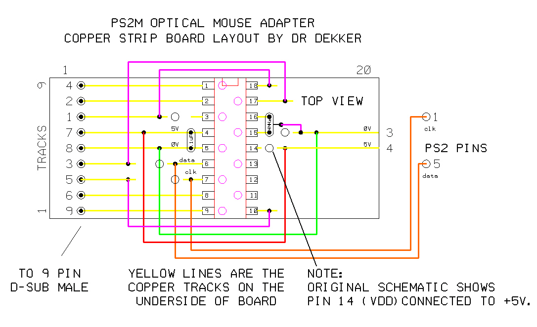
| PS2M Stripboard Layout | ||
 |
||
| Previous Image | Next Image | ||
|
Description: Here's a typical stripboard layout for the PS2M design. Note that the +5V supply to pin 14 (Vdd) is cut - contrary to the original schematic. I couldn't get it to work otherwise. Maybe due to me using a ceramic resonator in lieu of the crystal and capacitors - I don't really know!
Picture Stats: Views: 2143 Filesize: 196.58kB Height: 768 Width: 1024 Posted by: DrDekker at January 30, 2007, 12:09:17 AM Image Linking Codes
|
||
| 0 Members and 1 Guest are viewing this picture. |
| DrDekker Posts:325 | January 30, 2007, 12:46:19 PM Oops - missed that bit off! It's a good ol' PIC16F84A. |
| HellCoder Posts:279 | January 30, 2007, 06:44:46 AM What is the name of the chip ? |