|
|
| Homemade hardware 2 | ||
 |
||
| Previous Image | Next Image | ||
|
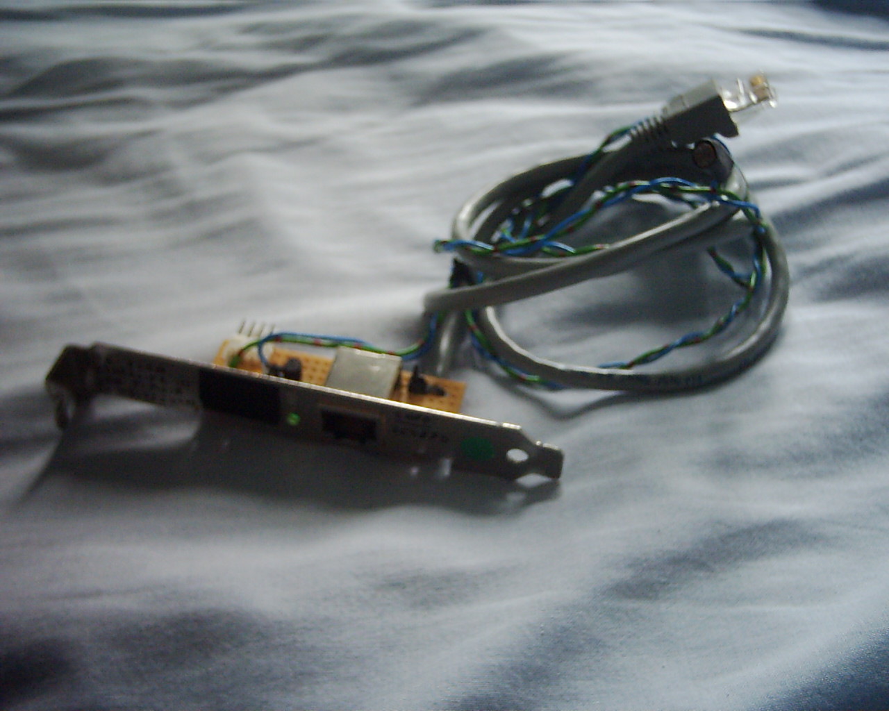
Description: Now why would anyone build a network device with an "input" lead and "output" connector onto a back panel plate? Answer :- Its a extender to allow a 3COM PCMCIA network card to function inside a tower, and to allow easy plugging and unplugging of cables and easy visibility of the LED on the adaptor lead via a LDR style circuit. Apart from that it reduces connector strain on the card/improves case air circulation by filling up a slot...etc. Picture Stats: Views: 3651 Filesize: 220.84kB Height: 768 Width: 1024 Posted by: Hodgkinson at August 21, 2006, 03:29:49 PM Image Linking Codes
|
||
| 0 Members and 1 Guest are viewing this picture. |
| stevieu Posts:84 | June 07, 2009, 10:38:29 PM Great idea  I'd like one of these  Steve |
| Hodgkinson Posts:1080 | March 25, 2008, 10:21:30 AM A much better photo can be found here. (2.07MB) |
| Hodgkinson Posts:1080 | December 18, 2007, 06:08:19 PM The LED power comes from the PSU, via that little 4-pin floppy header on the board. The idea was that the LDR on the end of those twisted wires there was to be tacked to the PCMCIA dongle just next to the link LED, which in turn controlled the green LED via a NPN transistor, so I could tell if the network was functioning correctly from the back of the tower. Note-It’s never actually been tested, since I've never actually got the 3C589D network card to work in my A1200T. Grrr. Hodgkinson. |
| rkauer Posts:3263 | December 17, 2007, 02:30:45 AM I say this is a brilliant idea! Do you feed the LED via the ethernet cable or directly from the PSU? |
| keropi Posts:2466 | August 22, 2006, 12:38:33 PM nice work! :-) |