|
|
| resoldering 040 to 060 in bppc | ||
 |
||
| Previous Image | Next Image | ||
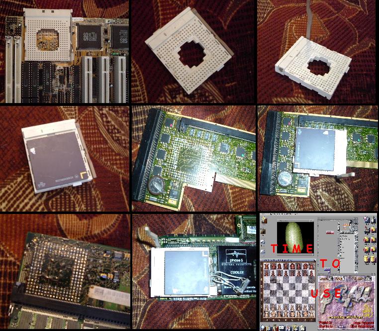
Description: 060 was take from old dead blizzard 060 board (only CPU was good, power of board was dead). Soket was take from i486 board. Resoldering by pump/soldering iron/and some russian vodka  Picture Stats: Views: 4284 Filesize: 142.85kB Height: 768 Width: 1024 Posted by: kas1e at October 18, 2005, 02:56:20 PM Image Linking Codes
|
||
| 0 Members and 1 Guest are viewing this picture. |
| Boot_WB Posts:1326 | September 04, 2013, 07:20:33 PM 8.5 years later, and I've just read your reply! I must have missed it the first time around, and just found this gallery entry again  Dude, I share your pain in the process of desoldering. Worth it though to personally upgrade your own accelerator card for the first time. See you here again in a few years. |
| kas1e Posts:430 
| November 03, 2005, 07:32:04 PM In this socket, i not use 2 line of pins. (btw,it is easy to push out or push in any pins to any place (without resoldering, just put in/out by hands)). If you look at 4 and 8 pict, you can see that socket with cpu have 2 free line of pins. And angle with 4 pins just unused. Soket type yes, i486. Older PC matherboard. Take a look on picts (but picts is totally ugly, sorry). free lines:   unused angle (from these 2 lines)  Btw, in azine4 (from http://www.azine.nu/archive.shtml) i found some info about sockets too (if you interesting), here is little translate from amigaworld (i do not remember who did it): --- Finding a PGA-socket? The next step was to find a PGA-socket suitable for the 68060. This turned out to be the hardest part of the entire project. I looket all over Europe without result, including all known companies which repair and make Amiga gear. Luckily I had an old Apollo 4060-accelerator in a corner at home. I don't use it anymore as I have a CyberstormPPC in my A3000 nowadays. I desoldered the socket from the Apollo 4060-accelerator which took nearly four hours due to all the pins which had to be cleaned, and obviously they all fell out of the socket which meant I had to rebuild the socket using a piece of cell foam as a base plate until I could squeeze the pins back at their place i the matrix. Efter this job I deserved a break and a pot of coffee for the next concentration exercise, that is, soldering the socket to my BlizzardPPC board. Here is a shome picts from azine:  |
| Boot_WB Posts:1326 | November 01, 2005, 04:27:17 PM Hi, dragging up an old facourite of a thread here, but: Looking at the photos there are 4 pin holes missing from the socket - how did you get around this problem? |
| Narayan Posts:254
| October 22, 2005, 09:16:58 PM It's big. This thing poundingly breaks concrete. |
| Karlos Posts:16882 | October 20, 2005, 01:47:28 AM @Kas1e The ZIF socket is a nice touch man :-) |
| kas1e Posts:430
| October 19, 2005, 04:01:37 PM @delshay yes, 603e without scsi.here is empty slot for scsi, i think i will try to think about scsi solder on bppc. what about socket: no, blizzpcc do not have any socket for cpu. cpu was soldered directly (on all bppc accelerators). |
| delshay Posts:1009
| October 19, 2005, 09:06:04 AM i take this blizzard PPC does not have a scsi..it seems there is no way to put the lead on. why a 486 socket? ..blizzppc already have a socket on them..correct me if im wrong.. |
| kas1e Posts:430
| October 19, 2005, 07:32:22 AM @j-golden with termo drier, soldering iron and pump. but termo drier as i said before, can resolder few resistors under cpu. So, best way: a bit use termo drier (for bounds), and for center of cpu - soldering iron + pump. If it will first time work like this - maybe it will take 1-2 days, if no - 1-2 hours of all work. btw, mainly help with it i take from man registered here as StormLord (from greece). take a look on this posts, maybe found some new info about it: http://www.amiga.org/forums/showthread.php?t=14501 http://www.amiga.org/forums/showthread.php?t=18278 |
| J-Golden Posts:1333 | October 19, 2005, 07:09:10 AM WHOA!!!! :-o I'm up for hacking just like the next guy, but this is like AWESOME!!! How did you do the solder/resolder work? I've never had a steady hand for it and imgining this kinda work... well, as I said, AWESOME!!! |
| kas1e Posts:430
| October 19, 2005, 05:08:34 AM @frankbrana Flash update was done after resoldering. And btw, someone told me , that i can't load workbench with new 060, but with old 040 flash - it is not true. After i solder new 060, i power-on amiga and try to load wb. Load was complete. Next, i update flash (in cli console of loaded wb). But, in _any_ case it can be loaded from floppy or without startup-sequence. What about oscilator,resistor, here is 2 thinks: multiplier resistor (for 040 it was divide by/2(so 040x33mhz = 66mhz oscil, for 060 just move this resistor to other side) and power black coil for power. Was 3.3 move to left side and have 5.0 So, steps: 1. put off 040, put on 060 2. change divide resistor to new position. 3. change black coil to new position (from 3.3v to 5v) 4. That all, power on and update flash. btw, under cpu 3-4 little 'power regulate' resistors, it is very easy to resolder they with cpu, but it can be change on any other resistors this kind. Main rule - slow work. If you will want to do it this, write me,i send you picts about coil and divide resistor (where is they must be placed). |
| FrankBrana Posts:178
| October 19, 2005, 12:15:55 AM @karlos The jumper thing I told in the other post, its supposed to change the working mode in the voltage regulator. Afaik it can deliver both +3.3v and +5v. |
| Karlos Posts:16882 | October 19, 2005, 12:06:17 AM What about voltages? The 68060 is a 3.3v part. Does the regulator need tweaking or what? |
| FrankBrana Posts:178
| October 18, 2005, 11:43:10 PM Congrats! I have heard many time that kind of conversion was possible, but the info I found was contradictory. Afaik, it involves 1- Update the flash to the 060 version while the card its still working with the 040 2-Remove the 040 and solder 060 3- Mach the oscilator and/or the multiplier with the 060 frecuency 4- Move the "jumper" (yeah, that black blocky thing) just near the 060 and the multiplier resistors, to the other possible position. 5- You´re done? Can you, please, explain us how you did that? Thank you in advance. |