|
|
| DoomMaster’s Doomsday Device | ||
 |
||
| Previous Image | Next Image | ||
|
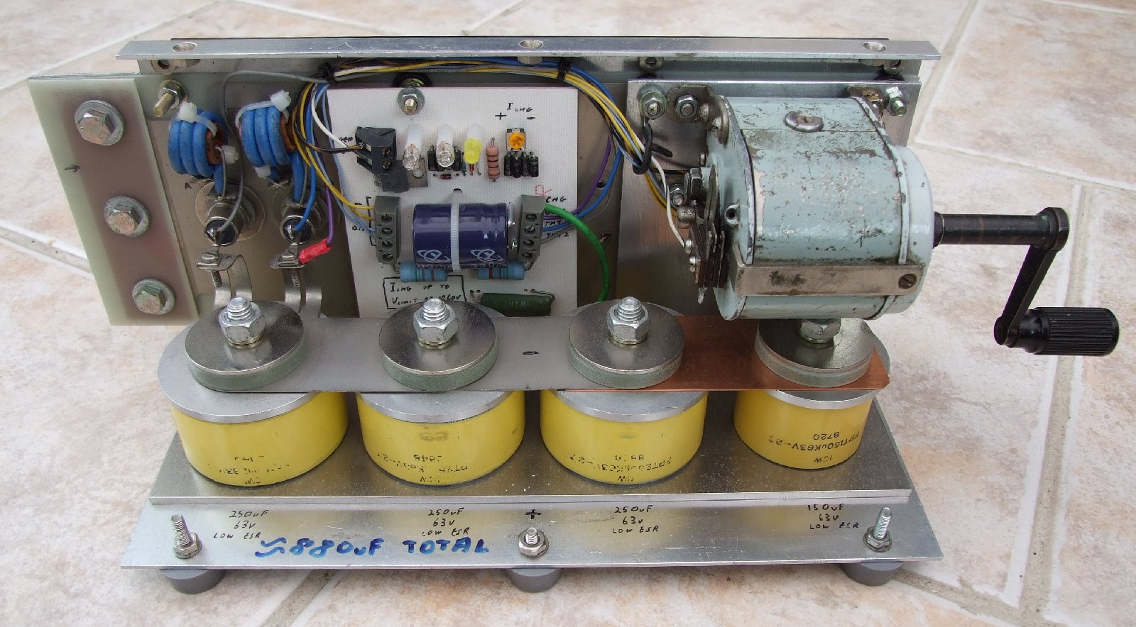
Description: Heh. Not quite. It’s actually a high current EMP pulser that I built (Because I could…), comprising of a total of 900uF (Measured to be 880uF) of specialist low-ESR capacitors charged up to 63v from a old telephone magneto and fired using two high-current thyristors. The connections are made through the big bolt-together plates on the left-hand side, and the white PCB that you can see serves to limit the charge current and voltage to the main capacitors and the trigger capacitor (Which is mounted on the board). I bought the original unit, from which this was built, from the SNADARC amateur radio rally for £10. The guy at the stall told me that the unit came out of NMR / MRI scanner, and that’s all I know; and (Regrettably) I didn’t bother to take a “Before modification” photo at the time. The parts that have been changed or added from its original form include the magneto (Also bought from the rally) and associated mounting plate, the white PCB, the rubber feet, the copper strap (Originally the smaller of the 4 capacitors was separate), most of the wiring and all the notes that I’ve scrawled onto it. I’d really like to know more about what the original unit was actually used for (If you do, my email address is under my account page…). Identification and part info for the original unit: - The original unit contained two PCB’s; one as a connection backplane (Still in use), labelled JB021 ISSUE 3, serving the two (Unlabelled) high current thyristors; and a smaller PCB connecting to a bank of MOSFETs, power resistors, and the smaller of the low-ESR capacitors, labelled JB020 ISSUE 2. - There is a large black heatsink on the back of the unit, covering the entire length and height. Onto this was mounted the following components (All components connect through to the JB020 ISSUE 2 board): 3x IRF1930 100v 11Amp P-MOSFETS (All insulated). 1x BUZ15 50v 45Amp N-MOSFET (Insulated). 2x Power resistors, 0.3R, paralleled, 5% tolerance, probably 5W rated each. 2x Power resistors, 0.1R, paralleled, 5% tolerance, probably 5W rated each. - The low ESR capacitors comprised of 3x 250uF 63v (Paralleled together) and 1x 150uF 63v (Separate from the rest). All 4 of the capacitors are hollow through the centre, and bolts are used to make the connections to the plates at either side, hence the insulator disks above each one. The only remaining capacitor with readable markings (The 150uF one) is labelled: 10W FPT150uK63V-27 8720 - Unusually, the chassis of the unit is in fact the positive connection to the capacitors (Assuming that the capacitors are polarity sensitive), judging by the thyristor connections. When the thyristors conduct, conventional current flows out of the positive plate of the capacitors, out of the unit, through the load, back into the unit, through the thyrisors, and back to the negative plate of the capacitors. - The thyristors are connected in series with a resistor/choke parallel network, before they are connected in parallel with one another. A photo of the JB020 ISSUE 2 board and some of the original components can be found here (The markings on the PCB show where the original components were connected): http://www.booni.info/downloads/Pulser_parts.jpg Picture Stats: Views: 1804 Filesize: 292.13kB Height: 768 Width: 1024 Posted by: Hodgkinson at July 05, 2008, 06:27:34 PM Image Linking Codes
|
||
| 0 Members and 1 Guest are viewing this picture. |
| Hodgkinson Posts:1080 | July 14, 2008, 06:37:32 PM > Have you tested it yet? Of course :-D I actually tried it with a loop antenna for the 2m amateur band, but I didn't hear anything on the rig (Probably needs a resonant circuit somewhere, then it would be interesting...) Its also good for frying wire-wool - Take a single strand or two and it completely vaporises in a puff of white sparks (Just like real sparklers) :crazy: It can also make small (I mean tiny) loops of wire jump around if you sit them on top of a small coil wired to the output - But there's not enough energy stored there for anything like what these guys build for a living (Heh, I have 2 of their books :crazy: ) |
| Karlos Posts:16867 | July 13, 2008, 10:28:58 PM Doesn't this need to be attached to a loop antenna or something through which to dump the current in order to work? Have you tested it yet? |
| Hodgkinson Posts:1080 | July 08, 2008, 06:58:46 PM :devildance: :flame: |
| tokyoracer Posts:1590 | July 08, 2008, 06:42:38 PM Shove it next a WinPC and then slowly turn increase the pressure. Great fun I bet. |
| Hodgkinson Posts:1080 | July 07, 2008, 10:27:30 PM 63 volts (That’s the cap rating) ;-) It only stores about 1.8 joules of energy, so there isn't really much energy there. It doesn't have a purpose (Yet) - I only built it because I could :-D The two neons at the top of the PCB serve to limit the magneto output to ~90v. I’m using a CRD (Constant current diode) as part of the current-limit circuit (As a reference only), and they’re rated up to about 100v, hence the need to limit the input voltage. Without the current-limit circuit the magneto would of been extremely rough to turn when you’d start charging it due to the apparent short-circuit load. When the voltage reaches about 60v, a string of zeners starts to conduct, causing the LED to flash and preventing the base voltage on the TIP50 buffer transistor from being allowed to rise any higher, thus limiting the maximum voltage attainable. Just a little bit of background info there ;-) BTW: I actually built a hand-cranked xenon-flasher in a lantern torch. That charged a 4uF paper capacitor up to nearly 800v straight from the rectified output of the generator (An AC low-speed motor similar to those used to rotate microwave oven turntables). I even added some neon’s onto it for signalling purposes...And spent £20 to have the generator winding re-wound once… Then my Dad got hold of it and managed to sheer some of the teeth off in the generator gearing :madashell: - Now it's packed away in bits in a box, looking sorry for itself :-( |
| rkauer Posts:3263 | July 07, 2008, 12:30:46 PM Or is it for metal point solder? |
| rkauer Posts:3263 | July 06, 2008, 09:34:36 PM Looks like a xenon lamp flash manual "charger". What is the voltage level on the thing after fully charged? |
| Hodgkinson Posts:1080 | July 06, 2008, 09:30:05 AM :lol: |
| adolescent Posts:3056 | July 06, 2008, 04:49:11 AM At first glance I thought you built a really powerful pencil sharpener... :-) |